Posts

MESH ANALYSIS

Image
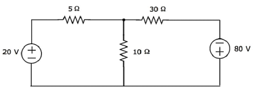
Introduction:                            In Mesh analysis, we will consider the currents flowing through each mesh. Hence, Mesh analysis is also called as  Mesh-current method .                          A branch is a path that joins two nodes and it contains a circuit element. If a branch belongs to only one mesh, then the branch current will be equal to mesh current.                          If a branch is common to two meshes, then the branch current will be equal to the sum (or difference) of two mesh currents, when they are in same (or opposite) direction. Procedure of Mesh Analysis:                          Follow these steps while solving any electrical network or circuit usin...

Ohm's Law

Image
Introduction:                          One of the most basic and important laws of electric circuits is Ohm’s law. Ohm’s law deals with the relationship between current, voltage and resistance.                            Georg Simon Ohm, a German physicist was the first to verify Ohm’s law experimentally. That  is why the law is well known as Ohm’s law. Ohm’s law first appeared in the book written by Georg Simon Ohm in 1827. Statement:                          Ohm’s law states that "At constant temperature the voltage across a conductor is directly proportional to the current flowing through that conductor". V ∝ I                          The proportionality constant is written...

KIRCHHOFF'S LAWS

Image
 Introduction:                     A German physicist Gustav Kirchhoff developed two laws enabling easy analysis of interconnection of any number of circuit elements. The first law deals with the flow of current and is popularly known as  Kirchhoff’s Current Law ( KCL) while the second one deals with the voltage drop in a closed network and is known as  Kirchhoff’s Voltage Law  (KVL). Kirchhoff’s Current Law: Statement:                     The algebraic sum of the currents meeting at a junction in an electrical circuit is zero. Σ I = 0 As per the Kirchhoff’s Current Law, i1 + i2 – i3 – i4 – i5 + i6 = 0 -----------(1)                     The direction of incoming currents to a junction is taken as positive while the outgoing currents are taken as negative. The equation (1) can also be writt...

BASIC CIRCUIT COMPONENTS

Image
Electric Circuit :                     The interconnection of various active and passive components in a prescribed manner to form a closed path is called an electric circuit . Active Components:                 An active component is a component which supplies energy to a circuit. Active elements have the ability to electrically control electron flow.  Examples : Voltage sources Current sources (e.g. DC current source) Generators (such as alternators and DC generators) All different types of transistors (such as bipolar junction transistors, MOSFETS, FETs and JFET) Diodes (such as Zener diodes, photodiodes, Schottky diodes, and LEDs) Passive Components:               A passive component is a component which can only receive energy, which it can either dissipate, absorb or store it in an electric field or a magnetic field. Passive elements do not ...

Critical disruptive voltage and Visual critical voltage

Image
  Critical disruptive voltage:                       It is the minimum phase-neutral voltage at which corona occurs. Consider two conductors of radius  r  (cm) and spaced  d  (cm) apart.  If  V  is the phase-neutral potential, then potential gradient at the conductor surface is given by: g =[V/ r log e  (d/r)] volts / cm                In order that corona is formed, the value of g must be made equal to the breakdown strength of air.  The breakdown strength of air at  76 cm  pressure and temperature of  25ºC  is  30 kV/cm  (max) or  21·2 kV/cm  (r.m.s.) and is denoted by  g o . If  V C  is the phase-neutral potential required under these conditions, then, g o  =[V c / r log e  (d/r)] volts / cm where  g o  = breakdown strength of air at 76 cm of mercury an...

Corona

                      The phenomenon of ionisation of surrounding air around the conductor due to which luminous glow with hissing noise is rise is known as the corona effect. Corona Formation:                       Air is not a perfect insulator, and even under normal conditions, the air contains many free electrons and ions. When an electric field intensity establishes between the conductors, these ions and free electrons experience forced upon them. Due to this effect, the ions and free electrons get accelerated and moved in the opposite direction.                       The charged particles during their motion collide with one another and also with the very slow moving uncharged molecules. Thus, the number of charged particles goes on increasing rapidly. This increase the conduction of air b...

Nominal 'π' method

Image
                       In the nominal pi model of a  medium transmission line,  the series impedance of the line is concentrated at the centre and half of each capacitance is placed at the centre of the line. The nominal Pi model of the line is shown in the diagram below. In this circuit, By Ohm’s law By KCL at node a, Voltage at the sending end By ohm’s law Sending-end current is found by applying KCL at node c or Equations can be written in matrix form as Also, Hence, the ABCD constants for nominal pi-circuit model of a medium line are Phasor diagram of nominal pi model The phasor diagram of a nominal pi-circuit is shown in the figure below. It is also drawn for a lagging power factor of the load. In the phasor diagram the quantities shown are as follows; OA = V r  – receiving end voltage. It is taken as reference phasor. OB = I r  – load current lagging V r  by an angle ∅ r . BE = I ab...